|
|
Adjusting the Variable Height Holder for Agfa®, Microtek® and Similar Scanners |
|
|
|
Adjusting the Variable Height Holder for Agfa®, Microtek® and Similar Scanners |
|
You can adjust the Dual MF Film Holder For Agfa®, Microtek® and similar scanners to match the optimum film suspension height for your particular scanner.
Adjusting the Set Screws
|
|
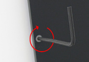
A small L-shaped hex key has been included
to turn/adjust the holder's set screws. Insert the hex key gently into
the socket as shown. BEFORE YOU START TO TURN THE KEY, MAKE SURE IT IS
FULLY INSERTED INTO THE SOCKET. Failure to do this could mean the key
will not engage and thus not fully turn the screw. This would cause
that adjuster to become out of sync with the others. If this happens,
you will need to start again at the zero position (see below). Turning the key to the right (clockwise) will extend the set screw. This will raise the holder (increase the film suspension height). If you lose this key, a 1/16" size, a replacement can often be purchased at a well-stocked hardware store and is usually found on the aisle where nuts and bolts are located. |
The Zero Position
You must begin your testing session with all of the set screws set to the "zero position" which means the bottom of the set screw is flush with the bottom surface of the holder. This can be accomplished via the following steps:
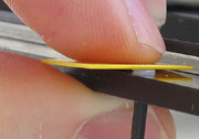 |
Turn the set screw so that it protrudes out slightly from the underside of the film holder. Place an object that is known to be flat against the top of the screw (the included square piece of colored shim stock is used in this example). |
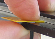 |
Maintain moderate pressure on the shim piece. Slowly reverse the set screw to the point the shim piece just comes into flat contact with the bottom of the holder. Do not turn any farther. If in doubt, repeat the procedure. Please note how the flat object only HALF covers the set screw so that you are able to better see/judge when the two come into contact. |
The Contact Surface of the Set Screws
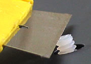 |
Since the set screws are molded nylon, the bottom surface of the set screw (the part of the set screw that actually touches the scanner's glass) can have some imperfections on it. If you prefer a flatter surface, you can easily trim the nylon with a sharp razor blade. |
Determining an Adjustment Increment
The bent "L" end of the hex key will serve as your adjustment indicator. If possible, always insert the key so that it points to the 12 o'clock position for the starting point before you begin adjusting. This will make it easier to estimate increments such as quarter and half turns. If you cannot insert the hex key at the 12 o'clock position (due to the previous adjustment you made for the zero position), insert the hex key as close as possible to the 12 o'clock position and then make a pencil mark to denote that offset point. This pencil mark will then be used as the starting point reference mark.
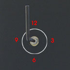 |
The following table shows
the linear relationship between key turns and height adjustment:
1/4 turn (e.g. from 12 to 3) = .2 mm |
If it took a number of individual increment adjustments to achieve your new optimal height, it is possible any incremental turning errors from each of the individual turns add up to an amount where there is a noticeable variation between individual set screw heights. Once you have determined your initial new optimum height, it can be a good idea to reposition the set screws to their zero point and adjust them back to the new height as a single adjustment (e.g., make an adjustment to +.6 mm in one adjustment of 1 turn vs. 3 individual quarter-turn adjustments).
The goal is to extend each of the holder's set screws an equal amount from the bottom surface of the holder in order to evenly raise the holder/film suspension height to match the optimum position for your particular scanner.
Methodology
To determine the optimum suspension height for your particular scanner, you will need to test by making multiple test scans using the same piece of film. This piece of film must be left in the same position within the holder for each of your test scans. Be very careful handling the loaded film holder between each test scan. Do not let the holder get dropped or slap it down onto your work surface because this could shift the film within the holder and affect your test scans. To really minimize the chance of film movement during the test scans, you want use the taping method to secure your film to the ANR Insert.
Utilize a fairly fine/small adjustment increment such as .2 mm (1/4 turn) from the beginning. Start with a zero height adjustment "base" scan and then create a series of scans where each subsequent scan adds .2 mm in height. You must adjust each one of the set screws AND adjust them by the same amount (e.g. 1/4 turn to raise the holder by .2 mm) in order to raise the holder evenly. Compare each new scan against the previous one. As long as each subsequent scan appears better than the previous one, continue to raise the holder by another increment and make another scan. Depending on the size of the adjustment increment used, it may take multiple adjustments before you actually notice an appreciable difference. Once the newest scan appears to be less sharp than the previous scan, the holder is past the optimal height. Reconfirm which previous scan was the sharpest and revert back to that height setting.
Caution: If you shim more than 1 mm in height, you must carefully recheck to make sure the holder (with T-locks inserted!!!) still clears the internal carriage that moves during scanning.
Seat the Holder Correctly
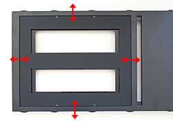 |
It is very important to make sure the holder is seated down into the drawer's frame. Once the frame has been placed down into the drawer, wiggle it gently back and forth in one direction and then the other. The holder is purposely loose in the drawer to make sure it doesn't get hung up on the sides of the drawer (which would potentially torque the holder or leave it positioned too high). |
Periodic Adjustment
It will be a good idea to periodically retest for
your scanner's optimum film suspension height. If internal changes within
the scanner occur over time, or if a set screw's position gets altered, it will
mean an adjustment is necessary.
E-mail Contact: scanning@betterscanning.com
All information contained in this website ©2024 by DSF OmniCorp, LLC and Doug Fisher. This information may not be reproduced in whole, part or spirit without written permission.
MF Film Holderä
Patent Pending