Using the Dual MF Film
Holderä For Agfa®, Microtek®
and Similar
It pays for itself quickly by allowing you to be more
efficient with your time and helping to minimize “handling damage” to your
film.
The Dual MF Film Holderä has been designed
to mimic the performance characteristics of the factory supplied medium format
holders. If you have problems concerning
color balance, system calibration and other software related issues, please
seek help with these issues from the manufacturer of your scanner (Microtek® Support)
or your third-party software supplier (e.g. Silverfast
or VueScan). The ScanTips.com
website is also a great resource to learn basic scanning techniques.
Inserting/Orienting
the Film Strip
Tip: You will probably find it easier to work with and align your film within the holder if you work on a light table or on a flat surface with a bright white sheet of paper lying underneath the film channels. The resulting higher contrast makes it much easier to align your film within the film channel.
If your film is relatively flat, orient the film as described in your scanner’s manual.
 If
your film strip has a pronounced arch/curl to it, place the film in the film holder so
it arches/curves upward from the base of the holder. You do not want the film’s arch/curl
to allow the film to “bow” down. When
the film’s arch/curl is oriented correctly, the T-Lock system (see below) will
help to minimize arching/curling by pressing it flat. If you flip your film over so that it arches
up, you may need to reverse or flip the final image. This is easily accomplished in Photoshop by
using the following menu commands: Image > Rotate
Canvas > Flip Horizontal.
If
your film strip has a pronounced arch/curl to it, place the film in the film holder so
it arches/curves upward from the base of the holder. You do not want the film’s arch/curl
to allow the film to “bow” down. When
the film’s arch/curl is oriented correctly, the T-Lock system (see below) will
help to minimize arching/curling by pressing it flat. If you flip your film over so that it arches
up, you may need to reverse or flip the final image. This is easily accomplished in Photoshop by
using the following menu commands: Image > Rotate
Canvas > Flip Horizontal.
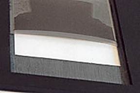
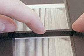
Aligning the Film
 Place the film within the film holding
channel so that it aligns straight over the Dual
MF Film Holderä window.
Place the film within the film holding
channel so that it aligns straight over the Dual
MF Film Holderä window.
(In this
picture, the film has not yet been locked down in place by the T-Lock, so you
see a larger than normal gap along the sides due to the film’s “arch”.)
The Dual MF Film Holderä window is slightly wider than the OEM film holder’s scanning aperture and thus will “mask”/frame your film frames differently. This was done purposely to accommodate cameras which produce slightly wider images (which the OEM holder will crop too much). The film channel (recessed area in which the film is placed) is slightly wider than normal by design. This makes it possible to scan out of specification films and images from cameras that do not center the image on the film (quite common). A clean pencil eraser is a handy tool for moving/final adjusting of film strips placed in the holder.
Important Notes on How The T-locks
Function
#1 – The T-locks are not
designed to fit into the holder very tightly in order to prevent premature wear
issues. The T-locks only need a slight
tension to stay in place and to push the film down flat. Don’t
not mistake a tighter fit for a better fit because a tighter fit can torque the
holder.
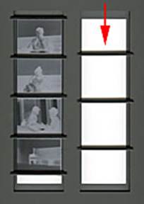 #2 - With the “dual” type of holders, if you only plan to use
one of the two film channels to just scan a single strip or frame of film, you
should also insert T-locks into the unused/empty film channel. When T-locks are only inserted in one film
channel, the holder can flex to the point T-locks may not fit tightly
enough. At a minimum, you should place
T-locks at positions approximately one quarter, one half and three quarters of
the length down the empty film channel. (See image on the left.)
#2 - With the “dual” type of holders, if you only plan to use
one of the two film channels to just scan a single strip or frame of film, you
should also insert T-locks into the unused/empty film channel. When T-locks are only inserted in one film
channel, the holder can flex to the point T-locks may not fit tightly
enough. At a minimum, you should place
T-locks at positions approximately one quarter, one half and three quarters of
the length down the empty film channel. (See image on the left.)
 #3 - Due to the tight design tolerances of
the T-Lock, if you don’t have the T-Lock inserted perpendicular to the film
channel, it will not hold itself within the film holding channel. If you insert it at an angle, it may not hold
well and may cause premature wear of the T-Lock.
#3 - Due to the tight design tolerances of
the T-Lock, if you don’t have the T-Lock inserted perpendicular to the film
channel, it will not hold itself within the film holding channel. If you insert it at an angle, it may not hold
well and may cause premature wear of the T-Lock.
#4 – Make sure the Dual MF Film Holderä is correctly seated down into the
scanner’s drawer. You want to make sure
the holder never sits up high enough to the point an incorrectly positioned
holder or a T-lock could come in contact with the scanner’s moving carriage.
Inserting the
T-Lock
 Grasp both ends of the T-Lock at the
“ears”. Align it so that it is perpendicular
to the sides of the Dual MF Film Holder’s
film holding channel.
Grasp both ends of the T-Lock at the
“ears”. Align it so that it is perpendicular
to the sides of the Dual MF Film Holder’s
film holding channel.
Now, gently
insert one side of the T-Lock bottom just barely down into the film
holding channel (1 mm or less).
Any more than this and you will risk damaging the T-Lock to the point
where it will not adequately hold itself in place.
 When applying pressure to the T-locks,
press on the thicker body of the T-lock as opposed to the thin “ears.” Now apply gentle pressure to the other side
of the T-Lock until it pops down into the film holding channel. Continue applying downward pressure evenly on
the T-Lock to firmly seat it into the film channel. While you don’t want to over exert pressure
on the T-Lock, you must push it in down far enough so that it holds the film
strip in place and keeps it from shifting.
When applying pressure to the T-locks,
press on the thicker body of the T-lock as opposed to the thin “ears.” Now apply gentle pressure to the other side
of the T-Lock until it pops down into the film holding channel. Continue applying downward pressure evenly on
the T-Lock to firmly seat it into the film channel. While you don’t want to over exert pressure
on the T-Lock, you must push it in down far enough so that it holds the film
strip in place and keeps it from shifting.
Always double-check to be sure that you have fully inserted
each T-lock down into the film channel.
A small gap between the ears and the top surface of the holder is normal
BUT you must make sure the T-lock is
fully inserted down into the holder (i.e. lightly pressing the film down
against the film channel). Failure to do so means the ears could stick up too high. This could result in damage to your scanner
because the scanning head assembly could hit the incorrectly inserted T-lock.
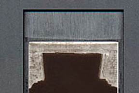
Common sense
dictates that, to avoid damaging your film, it is imperative you let the T-Lock
come into contact with the film only in the frame gaps between the images as
shown in the picture. Once the T-Lock is
secured into the holder, DO NOT try to move it or your film while the T-Lock is
secured in the holder. If an adjustment
is needed, pull the T-Lock out and then reposition items into the desired
location before reinserting the T-Lock.
The T-Lock System
Allows Infinite Adjustability
 One of the main advantages of the T-Lock
system is its infinite adjustability. If
you plan to scan only one or two frames, you can “mask off” just the frames you
wish to scan. By placing the T-Lock
right up against/next to the frames to be scanned, you maximize the T-Lock’s
film-flattening abilities. Lock down one
end of the single frame with a T-lock across the top end of the film channel
(where it can lock and fully grip/compress the film against the lower part of
the film channel all the way across).
One of the main advantages of the T-Lock
system is its infinite adjustability. If
you plan to scan only one or two frames, you can “mask off” just the frames you
wish to scan. By placing the T-Lock
right up against/next to the frames to be scanned, you maximize the T-Lock’s
film-flattening abilities. Lock down one
end of the single frame with a T-lock across the top end of the film channel
(where it can lock and fully grip/compress the film against the lower part of
the film channel all the way across).
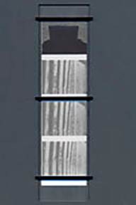 If you plan to scan a longer strip
consisting of multiple frames, there
are a few T-lock placement strategies that can be used. If you are using three T-locks, one technique
is to FIRST insert one T-Lock close to the middle of the strip at/over one of
the film strip’s frame gaps. Then insert
the second T-Lock at the top end of the film strip and the third T-Lock at the
other end of the film strip (see picture at left). If you are using four T-locks, the strategy
is pretty much the same where you first insert toward the middle and then work
your way outward. By inserting the
middle T-Lock(s) first, you minimize the chance of a wave or hump forming in
the middle of your film strip.
If you plan to scan a longer strip
consisting of multiple frames, there
are a few T-lock placement strategies that can be used. If you are using three T-locks, one technique
is to FIRST insert one T-Lock close to the middle of the strip at/over one of
the film strip’s frame gaps. Then insert
the second T-Lock at the top end of the film strip and the third T-Lock at the
other end of the film strip (see picture at left). If you are using four T-locks, the strategy
is pretty much the same where you first insert toward the middle and then work
your way outward. By inserting the
middle T-Lock(s) first, you minimize the chance of a wave or hump forming in
the middle of your film strip.
An alternative
technique is to place the film in the film channel, lock down one end of the
film strip with a T-lock across the top end of the film channel (where it can
lock and fully grip/compress the film against the lower part of the film
channel all the way across the opening instead of at just one point
on/along each side of the film channel), create a slight tension at the other
free end of the film by pulling on it the end of the strip, and then press in
the second T-lock at this other end.
Finally, insert the other T-Lock(s) in film frame gaps in the middle of
the strip. This technique really helps
to keep the film as flat as possible during the heat buildup of scanning. If
you plan to scan a longer strip consisting of one frame (e.g. 6x12 or 6x17),
I recommend this tension technique.
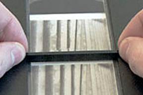
Removing the T-Lock
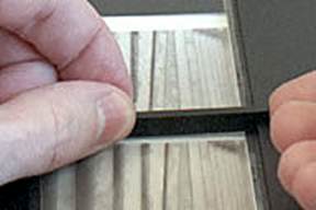 Due to the thinner “ears” on Dual MF Film Holderä
T-locks but thicker overall body, it is best to remove a T-lock by
grasping the T-lock toward the middle with both hands and gently pull upward. If
there is an occasion you need a little extra leverage, you can grasp the T-Lock
in the middle with one hand while inserting a fingernail under the end of the
T-Lock and gently pull up.
Due to the thinner “ears” on Dual MF Film Holderä
T-locks but thicker overall body, it is best to remove a T-lock by
grasping the T-lock toward the middle with both hands and gently pull upward. If
there is an occasion you need a little extra leverage, you can grasp the T-Lock
in the middle with one hand while inserting a fingernail under the end of the
T-Lock and gently pull up.
Correctly Placing
the Dual MF Film Holderä on Your Scanner
Once
the film is positioned in the holder, do
not let the holder drop or slap onto your work surface. If you do, an air cushion created by
dropping/slapping the holder can possibly reposition your film and/or cause
waves in the film. Always place the holder
gently down on any surface.
Adjusting the Dual MF Film Holderä Film Suspension Height
The Dual MF Film Holderä was designed to closely mimic the
suspension height of the OEM holders.
With the factory supplied OEM holder or the Dual MF Holder, you may find that a slight adjustment of
the suspension height can provide a more optimal scan (this will not be
necessary with every scanner). If you
wish to experiment and test this, four adjustable set screws have been
incorporated into the holder. Please
visit the following page for detailed instructions on this feature:
Adjusting the
Variable Height Holder for Agfa®, Microtek® and
Similar Scanners
Caution: If you shim more than 1 mm in height, you
must carefully recheck to make sure the holder (with T-locks inserted!!!) still
clears the internal carriage that moves during scanning.
Storing Your Holder – Very Important
Please follow
common sense in caring for your holder and…
DO store your holder at room temperature away from direct
sunlight and store in an environment where the holder will not be exposed to
large changes in temperature.
Do NOT leave T-locks inserted in the holder when the holder is
not in use.
Do NOT store your holder in its scanner
drawer. It is very important to store
your holder on a flat
surface. Consider turning the holder upside
down and placing it on the scanner’s glass bed (used for
transparency/reflective scanning) and lower the scanner’s lid so it provides
gentle and even weight on the holder
during storage. If you have another
surface that you know is flat, you could also place the holder on that with a wide book on top that weighs a few
pounds.
Click on the
following links to go to:
ORDER NOW -
Pricing and Ordering Page for ALL Products
Back to the Page You Were Previously
Viewing
Batch Scanning
Notes and Tips Page
Safety,
Return Policy, Warranty and Disclaimer Information
E-mail Contact: scanning@betterscanning.com
All information
contained in this website ©2024 by DSF OmniCorp, LLC and Doug Fisher.
This information may not be reproduced in whole, part or spirit without written
permission.
Patents Pending. All
intellectual property rights reserved.