Using the MF Film Holderä
It pays for itself quickly by allowing you to be more efficient with your time and helping to minimize “handling damage” to your film.
The MF Film HolderTM
has been designed to mimic the performance characteristics of the factory
supplied Epson® medium format holders. If you have problems concerning color
balance, system calibration and other software related issues, please seek help
with these issues from Epson® or your third-party software vendor. The
ScanTips.com
website is also a great resource to learn basic scanning techniques. (Epson®
3170 and 4180 users, please click
here for special notes.)
Tip: You will probably find it easier to work with and align your film within the holder if you work on a light table or on a flat surface with a bright white sheet of paper lying underneath the film channels. The resulting higher contrast makes it much easier to align your film within the film channel. A clean pencil eraser is a handy tool for moving/final adjusting of film strips placed in the holder.
|
Epson® recommends inserting the film so the emulsion side (dull side) is facing up and thus the manufacturer’s edge markings on the film appear to read backwards. If your film is relatively flat, orient the film this way first, but don’t be afraid to experiment with the orientation of the emulsion because some users claim they get better scans with the emulsion side down (most say they can’t tell the difference). If you scan your film “emulsion side down,” you may need to reverse or flip your image. This is easily accomplished in Photoshop by using the following menu commands: Image > Rotate Canvas > Flip Horizontal. |
|
If your film strip has a pronounced arch/curl to it, place the film in the film holder so it arches/curves away from the scanner glass. You do not want the film’s arch/curl to allow the film to “bow” down and come into contact with the scanner’s glass (usually causing “Newton Rings”). When the film’s arch/curl is oriented correctly, the ANR Insert (see below) will help to minimize arching/curling. |
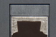 |
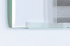
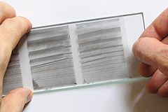
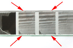
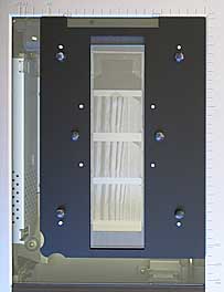
Place the film within the film holding channel so that it aligns straight over the MF Film Holderä window.
(In this picture, the film has not yet been pressed down into place by the ANR Insert, so you see a larger than normal gap along the sides due to the film’s “arch”.) |
The MF Film Holderä window is the same width as the Epson® film holder’s window and thus will “mask”/frame your film frames with the same constraints. The film channel (recessed area in which the film is placed) is slightly wider than normal by design. This makes it possible to scan out-of-specification films as well as images from cameras that do not center the image on the film (quite common). A clean pencil eraser is a handy tool for moving/final adjusting of film strips placed in the holder.
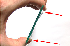
Hold the ANR Insert at an angle to your room’s light source to determine which side of the insert has the etched surface. The two images shown below will help you determine which are the etched and un-etched sides of the glass.
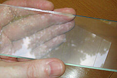 |
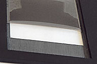
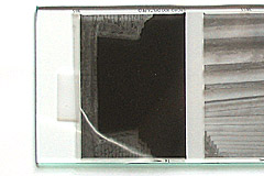
This first image shows the un-etched side of the glass. Notice the glare and the sharp/well defined reflection of the tree and clouds. You DO NOT want your film to come in contact with this side of the glass. |
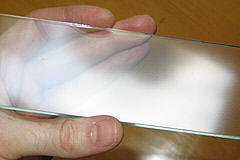 |
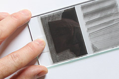
This second image shows the etched side of the insert (it is actually reflecting part of the same scene as shown above). However, please notice there are no defined shapes in this reflection. In practical terms, you cannot distinguish the reflection of the tree. This is the only side of the ANR Insert that should come in contact with your film! Place this side of the ANR Insert against the film already inserted into the holder’s film channel or tape your film to this side of the glass if you plan to utilize the taping technique (both discussed below). |
 |
The first method is simple. Film is placed normally in the holder and the ANR Insert is placed on top of the film so that the anti Newton surface is touching/against the film in the film holder. You must place the film into the holder so the film arches up and away from the scanner’s glass bed or the ANR Insert probably will not have any positive effect. |
Some films require more control. In this case, the strip of film can be mounted to the etched surface of the ANR Insert. This "package" is then flipped over and inserted into the MF Film Holder’sä film channel so that the film is facing toward the scanner’s glass.
Use a tape type that will
not leave a residue on your film. It should be fairly thin so that it can wrap
around the edge of the insert if necessary, yet still allow the insert to fit
into the holder’s film channel. You can buy expensive tape specifically
designed for scanner mounting from companies such as Kami although most people
find 3M’s “Magic Tape®” (it is also marketed as their “invisible”
matte tape) works just as well and it can be bought at most any decent office
supply store, Target, Wal-Mart, etc. Spend the extra few cents and only buy
the genuine high quality 3M product!!! Cut each piece of tape straight
using scissors. The serrated edge left by the tape dispenser will not work
as effectively as a scissor cut straight edge. TIP: Precut a number of tape
pieces so that you save time and won’t have to stop to cut more tape as you
process multiple strips/pieces of film.
Begin by placing the insert on a dust free surface so the etched/ANR/dull surface faces up. Make sure the surface on which you place the insert will not scratch the anti-Newton Ring glass. I recommend a 3M® microfiber cloth for a good soft and relatively dust free surface. These cloths are great for cleaning the ANR Insert as well as your scanner’s glass. Wal-Mart sells these for just a few dollars or they can usually be found in any store that sells optical products.
 |
Decide which film orientation is best. If your film has a serious arch running cross-wise, you want to orient the film so that the edges curl away from the glass (as shown in the picture on the left). You DO NOT want to orient the film so that the center of the film bows away from the glass in the middle. Improper orientation could lead to poor focus and/or Newton Rings if the bowing is great enough. Correct orientation will allow the sides of the film channel to help flatten any curling or arching along the long sides of the film. |
Epson® recommends inserting the film so the emulsion side (dull side) is facing up and away from the scanner’s glass and thus the manufacturer’s edge markings on the film appear to read backwards (as viewed when the insert is placed into the holder). If your film is relatively flat, orient the film this way first, but don’t be afraid to experiment with the orientation of the emulsion. If you scan your film “emulsion side down,” you will need to reverse or flip your image to make it laterally correct. This is easily accomplished in Photoshop by using the following menu commands: Image > Rotate Canvas > Flip Horizontal.
 |
You most likely will find it easiest to successfully attach your film to the insert if you pre-attach the tape at the point(s) on the ends of the film strip/piece before you start the actual placement procedure. Attach the tape to the blank frame spacing found at each end of the film strip. Don’t let the tape cover any part of your image you wish to scan… |
 |
…Or if you don’t have enough blank frame spacing left on the end of your film strip, tape along each side as shown in this picture (thus utilizing two small pieces of tape on each end). If using this latter method, make sure the tape does not wrap too far around onto the other side of the glass. Otherwise the tape could appear in your scans. Additionally, make sure to create a little cross-wise tension between the two pieces of tape when applying the second piece of tape to ensure cross-wise flatness. |
 |
Attach one end of your film to the insert. |
 |
Now attach the other end of your film but remember the key goal to accomplish when taping down the second end of the film is to create a moderate tension across the film. This helps minimize any lengthwise curling of the film. This is accomplished by pulling moderately on the film before you attach the tape and then maintaining that tension as you tape the film to the glass. (The other end of the film should already be taped down and thus allow you to create this tension). |
 |
Make sure to orient your film so it leaves an even amount of space on each side. This ensures that both sides of the film will be in contact with the film channel’s sides/ledges. |
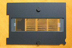 |
Now gently flip the insert over and place it into the MF Film Holder’sä film channel. When looking at an insert placed into the holder (as in the image to the left), the glass is on top of the film. The ANR Insert is never positioned between the film and the scanner’s glass bed. |
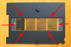 |
Look down through the insert’s glass to check that all edges and ends of the film are oriented so they are not obscured by the sides OR ends of the film channel. Adjust the insert’s placement within the MF Film Holder’sä film channel as necessary. |
Finally, carefully place the film holder in its normal correct position on the scanner’s glass bed. Check to make sure the insert did not shift within the holder when you moved the holder+insert onto your scanner.
You should now be ready to scan!
Note: The ICE feature may not work well with anti-Newton Ring glass. The compatibility varies by film type, so it may need to be turned off. If you wish to use ICE, please order the optional T-locks (see how optional T-locks are used) when you place your order.
***Common sense dictates that to avoid damaging your film, once the ANR Insert is placed into the holder DO NOT try to move it or your film while the ANR Insert is in the holder. If an adjustment is needed, pull the ANR Insert out and then reposition your film into the desired location before reinserting the ANR Insert.
 |
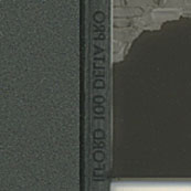
The MF Film Holderä should be placed directly on the scanner’s glass so that the film holder channel and rubber bumpers face up (away from the scanner glass) as shown in the picture on the left. |
Once the film is inserted in the holder, do not let the holder drop or slap onto your work surface or the scanner’s glass. If you do, an air cushion created by dropping/slapping the holder can possibly shift your film’s position as well as cause waves in the film. Always place the holder gently down on any surface.
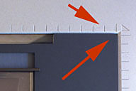 |
It is important to make sure the MF Film Holderä is placed in the upper right-hand corner of the scanner (nested directly against both the top and right sides of the scanner bed). Accurate positioning makes sure the calibration notch is correctly positioned and will ensure repeatability if using VueScan’s batching scan function to scan multiple frames on your film strip. |
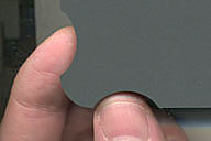 |
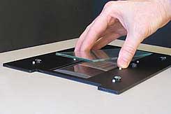
A finger grip has been built into the each lower corner of the Dual MF Film Holderä to help you get a grip on the holder and lift the corners from the scanner’s glass. After using the finger grip to lift the corner off the glass, you should be able to easily slide your hand under the Dual MF Film Holderä in order to fully grasp the holder and then remove it from the scanner. |
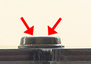 |
The surface on top of the rubber bumpers can have a great deal of grip/stick. If the bumpers begin to stick to the scanner’s transparency adapter when you open the lid, put an extremely fine coat of baby/talcum powder dust on the top surface. Gently and lightly wipe off any excess powder. This will eliminate the sticking. |
Adjusting a Variable Height Holder
The optimum film suspension height for your particular scanner unit may actually vary from the standard 1 mm film suspension height provided by the OEM Epson holder and the Fixed Height MF Holders. If your scanner's optimum height is different than 1 mm, the variable height holder allows you to compensate for this difference!
Adjusting the Set Screws
|
|
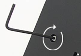
A small L-shaped
hex key has been included to turn/adjust the holder's set screws.
Insert the hex key gently into the socket as shown. BEFORE YOU
START TO TURN THE KEY, MAKE SURE IT IS FULLY INSERTED INTO THE
SOCKET. Failure to do this
could mean the key will not engage and thus not fully turn the
screw. This would cause that adjuster to become out of sync with
the others. If this happens, you will need to start again at the
zero position (see below). |
The Zero Position
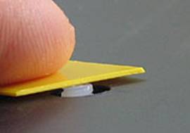
You must begin your testing session with all of the set screws set to the "zero position" which means the bottom of the set screw is flush with the bottom surface of the holder. This can be accomplished via the following steps:
|
|
Turn the set screw so that it protrudes out slightly from the underside of the film holder. Place an object that is known to be flat against the top of the screw (the included square piece of colored shim stock is used in this example). |
|
|
|
|
|
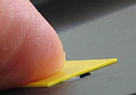
Maintain moderate pressure on the shim piece. Slowly reverse the set screw to the point the shim piece just comes into flat contact with the bottom of the holder. Do not turn any farther. If in doubt, repeat the procedure. Please note how the flat object only HALF covers the set screw so that you are able to better see/judge when the two come in contact. |
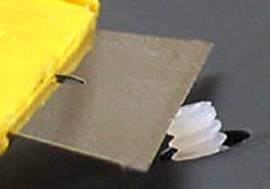
The Contact Surface of the Set Screws
|
|
Since the set screws are molded nylon, the bottom surface of the set screw (the part of the set screw that actually touches the scanner's glass) can have some imperfections on it. If you prefer a flatter surface, you can easily trim the nylon with a sharp razor blade. |
Determining an Adjustment Increment
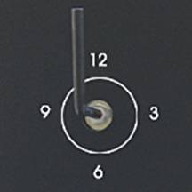
The bent "L" end of the hex key will serve as your adjustment indicator. If possible, always insert the key so that it points to the 12 o'clock position for the starting point before you begin adjusting. This will make it easier to estimate increments such as quarter and half turns. If you cannot insert the hex key at the 12 o'clock position (due to the previous adjustment you made for the zero position), insert the hex key as close as possible to the 12 o'clock position and then make a pencil mark to denote that offset point. This pencil mark will then be used as the starting point reference mark.
|
|
The following table shows the linear relationship between key turns and height adjustment:
1/4 turn (e.g.
from 12 to 3) = .2 mm |
The goal is to extend each of the holder's set screws an equal amount from the bottom surface of the holder in order to evenly raise the holder/film suspension height to match the optimum position for your particular scanner.
If it took a number of individual increment adjustments to achieve your new optimal height, it is possible any incremental turning errors from each of the individual turns add up to an amount where there is a noticeable variation between individual set screw heights. Once you have determined your initial new optimum height, it can be a good idea to reposition the set screws to their zero point and adjust them back to the new height as a single adjustment (e.g., make an adjustment to +1.2 mm in one adjustment of 1.5 turns vs. 6 individual quarter-turn adjustments).
Methodology
To determine the optimum suspension height for your particular scanner, you will need to test by making multiple test scans using the same piece of film. This piece of film must be left in the same position within the holder for each of your test scans. Be very careful handling the loaded film holder between each test scan. Do not let the holder get dropped or slap it down onto your work surface because this could shift the film within the holder and affect your test scans. To really minimize the chance of film movement during the test scans, you want use the taping method to secure your film to the ANR Insert.
Different methods can be used for testing. If you have never experimented with shimming your holder, the slower methodical approach may be the best. Utilize a fairly fine/small adjustment increment such as .2 mm (1/4 turn) from the beginning. Start with a zero height adjustment "base" scan and then create a series of scans where each subsequent scan adds .2 mm in height. You must adjust each one of the set screws AND adjust them by the same amount (e.g. 1/4 turn to raise the holder by .2 mm) in order to raise the holder evenly. Compare each new scan against the previous one. As long as each subsequent scan appears better than the previous one, continue to raise the holder by another increment and make another scan. Depending on the size of the adjustment increment used, it may take multiple adjustments before you actually notice an appreciable difference. Once the newest scan appears to be less sharp than the previous scan, the holder is past the optimal height. Reconfirm which previous scan was the sharpest and revert back to that height setting.
If you have previously done shimming tests and already know your particular scanner requires a significant amount of height adjustment, you may want to start out utilizing a relatively "coarse" adjustment increment such as .4 mm or .6 mm to quickly determine the general range for the optimum focus height. Once you have determined the general range, make additional test scans using a more "fine" adjustment increment such as .2 mm. Scan at both a +.2 mm and - .2 mm adjustment to determine whether you need to progress in a plus or minus direction. This approach can save you time if your particular scanner's optimum height is quite a bit more than the standard 1 mm.
Placement
|
|
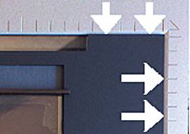
The inside edges around an Epson scanner's glass bed are not straight up and down, they are beveled. With certain scanners, it will be necessary to raise the holder a significant amount. When the adjustment amount exceeds 1.5 mm, the bottom edge of the holder will start to rise and be able to encroach into the beveled area. Pay attention in order to keep the holder positioned correctly right above the edge of the glass. |
Click on the following links to go to:
ORDER NOW - Pricing and Ordering Page for ALL Products
Back to the Page You Were Previously Viewing
Epson® 3170/4180 Special Notes Page
Batch Scanning Notes for the MF Film Holderä Page
E-mail Contact: scanning@betterscanning.com
All information contained in this website ©2026 by DSF OmniCorp, LLC and Doug Fisher. This information may not be reproduced in whole, part or spirit without written permission.
Patents Pending. All intellectual property rights reserved.